|
Theory of Linear Mappings
The aim of this project is to discuss the mappings used in Descriptive Geometry and their generalisations from both a synthetic and analytic point of view.
|

Intermediate image

Undistorted image
|
The Elementary Setting: Central Projection - Similarity
In elementary Descriptive Geometry we are concerned with mappings of the Euclidean 3-space onto a Euclidean plane. Usually one uses mappings that arise as follows: A projection on an (intermediate) plane is composed with a similarity onto the plane of the final picture.
For example, if you take a photograph, then you first apply a central projection onto the plane of the film in your camera. Next, the image on the film (the intermediate image) is enlarged to give the picture for your album. Your final picture is similar to the image on the film. It has the same proportions.
|

Distorted by an affinity
|
Central Projection - Affinity
On the other hand, one could also apply an affinity to the intermediate picture on the film. This procedure is rather unusual, as it gives a final image which is more or less distorted. Nevertheless an affinity preserves lines, the parallelism of lines and affine ratios, in particular midpoints.
|

Distorted by a collineation
|
Central Projection - Collineation
Even worse: A collineation is used to get the final image from the picture on the film. A collineation preserves lines, but not the parallelism of lines. Hence the rectangular picture of the film appears as a general quadrangle.
|
|
|
Parallel Projection - Similarity
For many purposes it is sufficient to use a parallel projection rather then a central projection. Also here the projection on the intermediate plane is followed by a similarity to give the final image. E.g., the scaling factor of such a similarity is chosen so that the final image fits on a computer screen.
|
|
|
Examples
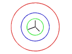
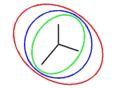
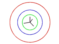
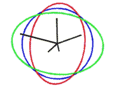
Each of the subsequent pictures is the product of a parallel projection to an intermediate plane in space and a similarity from that plane to the plane of your display; it shows the following:
|
Black:
|
The image of a Cartesian coordinate system in space.
|
|
Green:
|
The image of the unit sphere in space.
|
|
Blue:
|
The unit circle of the plane.
|
|
Red:
|
The ellipse of inertia.
|
For practical reasons, the units of the individual pictures are not the same. In fact, the real size (e.g. in centimetres) is unknown to the authors of this page, as it depends on the size of the screen YOU are currently using!
|
|
|
Orthogonal Projection - Similarity. The first picture arises from an orthogonal projection in three-dimensional space followed by a similarity of the intermediate plane to your screen.
You can see that there is a reduction of size, by comparing the radii of the blue and the green circle. In fact, reduction is 58.31%. As the ellipse of inertia is a circle, the picture is undistorted.
|
|
Oblique Projection - Similarity. The second picture comes from an oblique projection followed by a similarity. The green and the red ellipse are far from being circles (or "almost circles"), so the image is highly distorted. You can also see this from the images of the axes. The segment running to the left looks "much longer" than the others. The scaling is 70% and the projection rays form an angle of 59.75 degrees with the projection plane.
|
|
|
Orthogonal Projection - Similarity. Clearly, in mathematics there is no restriction on the dimension of space. The next picture shows you an image of a coordinate system in four-dimensional space. Usually, we are not used to see two-dimensional pictures of four-dimensional objects. So, if you look only on the image of the four coordinate axes, you will hardly be able to say if this image is distorted or not. However, as before, the essential data may be visualised by the green image of the unit sphere and the red ellipse of inertia. As both of them are circles, we have an undistorted image.
|
|
|
Oblique Projection - Similarity. Finally, we present a pictures showing the image of a Cartesian coordinate system in a five-dimensional space.
As you can see from the red ellipse of inertia, the image is highly distorted.
Further, you can read off the following property from the picture:
The red ellipse of inertia and the green ellipse (image of the unit sphere in space) have always common axes. The product of the lengths of two collinear semi-axes equals the unit length. So, the longer one semi-axis is, the shorter is the other. In fact, the polarity of the blue unit circle maps the points of the red ellipse on to the tangents of the green ellipse and vice versa.
|
|
|
Pohlke's Theorem
More generally, one may investigate mappings that arise as products of a parallel projection on an intermediate plane in three-dimensional space and an affinity of that plane on your screen.
By a theorem due to K. Pohlke (1853) such a mapping is nevertheless decomposable into a parallel projection on a plane in space and a similarity. In general, that "new" intermediate plane is different from the original one.
Pohlke's theorem also holds if the three-dimensional Euclidean space is replaced with an n-dimensional Euclidean space, but fails to hold (without further assumptions) whenever the image space has a dimension greater than two.
|
|
Singular Value Decomposition
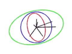
If a mapping arises as product of a parallel projection on an intermediate m-space in Euclidean n-space and an affinity of that m-space onto another Euclidean m-space then the mapping is also decomposable into an orthogonal projection and an affinity.
The picture on the left illustrates this for n = 7 and m = 2.
The eccentricity of the red ellipse of inertia indicates the deviation of that affinity from a similarity. This can be made more precise in terms of Linear Algebra via the singular value decomposition of our mapping. These so called singular values are just the lengths of the two semi-axes of the green ellipse. They are also called the principal distortion factors.
|
|
|
Publications
-
H. Brauner: Eine geometrische Kennzeichnung linearer Abbildungen, Monatsh.
Math. 77 (1973), 10-20.
-
H. Brauner: Abbildungsmethoden der konstruktiven Geometrie, Ber. math.-stat.
Sektion Forschungszentrum Graz Nr. 38 (1975) 1-10.
-
H. Havlicek: Einbettung projektiver Desargues-Räume, Abh. math.
Sem. Univ. Hamburg 52 (1982), 228-231.
-
H. Brauner: Zur Theorie linearer Abbildungen, Abh. math. Sem. Univ.
Hamburg 53 (1983), 154-169.
-
H. Havlicek: Die linearen Geradenabbildungen aus dreidimensionalen projektiven Pappos-Räumen, Sb. österr. Akad. Wiss., math.-naturw. Kl., Abt.II 192 (1983), 99-111.
-
H. Brauner: Zum Satz von Pohlke in n-dimensionalen euklidischen Räumen, Sb. österr. Akad. Wiss., math.-naturw. Kl., Abt.II 195
(1986), 585-591.
-
H. Brauner: Lineare Abbildungen aus euklidischen Räumen, Beiträge Algebra u. Geom. 21 (1986), 5-26.
-
H. Havlicek: Über die Abbildungsgleichungen einer Normalprojektion, Informationsblätter
Darst. Geom. (Univ. Innsbruck), Jg. 5 Heft 2 (1986), 33-36.
-
H. Brauner: Lehrbuch der Konstruktiven Geometrie, Springer, Wien New York, 1986.
-
H. Stachel: Mehrdimensionale Axonometrie, in: N.K. Stephanidis (ed.), Proceedings of the Congress of Geometry, Thessaloniki 1987, 159-168.
-
H. Stachel: The right-angle theorem in four dimensions, J. Theor. Graphics Computing 3 (1990), 4-13.
-
H. Stachel: Darstellede Geometrie und Graphische Datenverarbeitung, in: J.L. Encarnacao, J.Hoschek, J.Rix (eds.), Geometrische Verfahren in der Graphischen Datenverarbeitung, Springer, Berlin Heidelberg New
York 1990, 168-179.
-
H. Stachel. Parallel projections in multidimensional space. In H. P. Santo, editor, Compugraphics `91 - First Int. Conference on Computational Graphics and Visualization Techniques, volume I, pages 119-128, 1991. held in Sesimbra, Portugal, September 16-20, 1991.
-
H. Stachel, J. Szabó, H. Vogel: Ein Satz über die Zentralaxonometrie, Sb. österr. Akad. Wiss., math.-naturw. Kl., Abt.II 203 (1994),
3-11.
-
H. Havlicek: On the matrices of central linear mappings, Math. Bohem. 121 (1996),
151-156.
Preprint (PDF)
-
H. Stachel: Zur Kennzeichnung der Zentralprojektionen nach H. Havlicek, Sb. österr. Akad. Wiss., math.-naturw. Kl., Abt.II 204 (1995), 33-46.
-
H. Havlicek: Weak linear mappings — a survey, In: O. Röschel, H. Vogler (eds.): 107 Jahre Drehfluchtprinzip, (Proceedings of the Conference
on Geometry, Vorau, Austria, June 1 -7, 1997), Technical University of Graz 1999, pp. 76-85.
Preprint (PDF)
-
H. Stachel: On Arne Dür's equation concerning central axonometries, J. Geom. Graphics 8 (2004), 215-224.
Preprint (PDF)
-
B. Odehnal: Zur geometrischen Erzeugung linearer Geradenabbildungen. Österreich. Akad. Wiss. Math.-Naturw. Kl. S.-B. II 213 (2004), 43-69.
-
H. Stachel. Descriptive Geometry Meets Computer Vision - The Geometry of Two Images. J. Geom. Graphics 10 (2006), 137-153.
|
|
Quick Links
Hans Havlicek
Boris Odehnal
Hellmuth Stachel
A Tribute to Heinrich Brauner (1928-1990)
Descriptive Geometry
Characterisations of Geometric Transformations
Sitemap
|

